Common NPT Fitting Failures: How Proper Measurement Prevents Leaks and Blowouts

Table of Contents
- What Causes NPT Fittings to Leak?
- NPT vs. BSP Thread Mismatch: The Most Dangerous Error
- Over-Tightening NPT Fittings: Why More Torque Means More Leaks
- Thread Galling in Stainless Steel NPT Connections
- NPT Thread Sealant Mistakes That Cause Leaks
- Vibration-Induced NPT Fitting Failure
- Stress Corrosion Cracking in Brass NPT Fittings
- Worn and Aged Fittings: The Hidden Blowout Risk
- NPT Fitting Failure Prevention Checklist
- NPT Thread Size Quick Reference
- Build Leak-Free Pneumatic Connections
- FAQs
NPT (National Pipe Tapered) fittings are the backbone of compressed air, hydraulic, and plumbing systems across North America. Yet 60–90% of threaded fitting leaks trace back to human error during selection or installation — not to defective components. The good news: nearly every failure is preventable with accurate measurement, correct thread identification, and disciplined installation practices.
This guide breaks down the most common NPT fitting failure modes, explains exactly how each one leads to leaks or dangerous blowouts, and shows how proper measurement techniques prevent them. Whether you're building a new pneumatic system or troubleshooting an existing one, understanding these failure patterns will save you time, money, and safety headaches.
What Causes NPT Fittings to Leak?
NPT fittings leak primarily due to five root causes: thread standard mismatches (NPT vs. BSP), over-tightening, improper sealant application, thread galling, and vibration-induced loosening. Understanding these failure modes is the first step toward eliminating them from your compressed air or fluid system.
The table below summarizes each failure type, its typical consequence, and the measurement or installation step that prevents it:
| Failure Mode | What Happens | How Measurement Prevents It |
|---|---|---|
| Thread mismatch (NPT vs. BSP) | Spiral leak path; cannot seal regardless of sealant | Verify TPI with pitch gauge; measure OD with calipers; confirm 60° thread angle |
| Over-tightening | Thread deformation; port cracking (especially brass/cast iron) | Count exposed threads; limit to 1.5–3 wrench turns past hand-tight |
| Sealant errors | Open spiral leak path; system contamination | Apply sealant to male threads only; use correct type for material |
| Thread galling | Metal cold-welds; fitting seizes or cracks | Inspect threads pre-assembly; use anti-seize on stainless steel |
| Vibration loosening | Gradual preload loss; fatigue cracking at thread roots | Verify engagement depth; use thread-locking compound where needed |
Let's examine each of these in detail.
NPT vs. BSP Thread Mismatch: The Most Dangerous Error
The single most consequential fitting failure is mating an NPT fitting to a BSP (British Standard Pipe) port — or vice versa. This error is especially dangerous because the threads can partially engage, giving a false sense of security.
Why They Don't Mix
NPT threads have a 60° thread angle, while BSP uses 55°. The thread pitch also differs — for example, 1/8″ NPT is 27 TPI versus 28 TPI for 1/8″ BSP. Some nominal sizes share similar TPI values (both 1/2″ NPT and 1/2″ BSP happen to be 14 TPI), which means the threads can engage for several turns and feel "almost right." This is a trap.
The 5° angle difference means threads contact only at their crests — not along the load-bearing flanks. The resulting connection creates a spiral leak path that no amount of sealant or extra torque can reliably seal. Under pressure or vibration, this weak engagement fails — sometimes catastrophically.
How to Prevent NPT/BSP Mismatch
- Use a thread pitch gauge to verify TPI precisely — never estimate visually
- Measure thread OD with calipers and cross-reference against both NPT and BSP charts, since nominal sizes differ slightly between standards
- Check the thread angle with a profile comparator or gauge to confirm 60° (NPT) vs. 55° (BSP)
- Stop immediately if threads engage but feel rough or uneven after 2–3 turns — forced engagement destroys both components
If you're unsure whether your system uses NPT or BSP threads, our guide on understanding and measuring NPT thread size walks you through the identification process step by step.
NPT vs. NPTF: A Subtle but Important Distinction
NPT and NPTF (National Pipe Taper Fuel) threads look virtually identical but seal differently. NPT threads have a slight clearance between crests and roots that creates a spiral leak path — this is why NPT always requires sealant (PTFE tape or pipe dope). NPTF threads have modified crests and roots designed to crush together, forming a mechanical dryseal without sealant.
Mixing them without understanding this difference leads to unpredictable sealing, particularly in fuel and gas applications where sealant contamination is also a concern.
Over-Tightening NPT Fittings: Why More Torque Means More Leaks
It sounds counterintuitive, but over-tightening is one of the leading causes of NPT leaks. NPT connections are torque-sensitive by design — the taper causes threads to wedge together, creating elastic deformation that forms the seal. But this same taper acts as a mechanical wedge, making it remarkably easy to exceed the elastic limit.
What Over-Tightening Does
- Thread distortion: Permanent plastic deformation eliminates the spring-like elastic compression needed for sealing
- Port cracking: The taper places the female port in circumferential tension — brass, aluminum, and cast iron ports are especially vulnerable
- Seal crushing: Connections with supplementary O-rings can have the seal destroyed
- Galling initiation: Excessive force triggers the cold-welding process (see next section)
The Right Way to Tighten NPT Connections
ASME B1.20.1 specifies that for pipe sizes 2 inches or smaller, wrench tightening should not exceed approximately three threads past hand-tight. For low-pressure applications, 1.5 to 2 wrench-tight threads are often sufficient. Here's the recommended sequence:
- Verify threads are clean and free of burrs or debris
- Apply appropriate sealant to male threads only
- Hand-tighten to finger-tight engagement
- Count exposed threads and mark the starting position
- Wrench-tighten 1.5 to 3 additional turns (size-dependent)
- For directional fittings (elbows, tees), never back off to reorient — this breaks the sealant film and creates leak paths
Counting exposed threads before and after tightening provides an objective, repeatable gauge of engagement depth — far more reliable than subjective "feel" or torque readings, which vary with sealant type, material, and surface finish.
If you're working with brass ball valves or other NPT-threaded components, proper tightening technique is critical. Our 1/4 NPT ball valve selection guide covers installation best practices for these commonly over-tightened connections.
Thread Galling in Stainless Steel NPT Connections
Galling is adhesive wear where friction and pressure cause metal to shear from one thread surface and cold-weld to another. The result is scoring, thread damage, seizing, and — if the fitting is forced — cracking or structural failure. Stainless steel is the worst offender: its hardness and tendency toward self-adhesion make stainless-on-stainless NPT connections especially prone to galling.
Why Galling Is So Costly
Galling leaves behind metal particles that contaminate fluid systems, and the thread damage it causes is typically irreversible — the fitting must be scrapped. Internal port galling is particularly expensive because the port (often machined into a manifold or valve body) may need complete replacement.
How to Prevent Thread Galling
- Lubricate: Apply PTFE tape, anti-seize compound, or a thread sealant formulated for the material — especially critical for stainless steel
- Slow down: Avoid power tools for stainless NPT assembly; hand-tighten slowly to minimize friction heat
- Use dissimilar metals: Pair stainless male threads with brass or bronze female threads (or vice versa) to reduce the self-adhesion risk
- Limit reuse: NPT fittings should generally be replaced after 2–3 assembly/disassembly cycles, as each cycle wipes lubrication and work-hardens the thread flanks
If your system uses stainless steel push-in fittings or stainless steel couplers, always inspect threads for galling damage before each assembly.
NPT Thread Sealant Mistakes That Cause Leaks
NPT thread geometry intentionally allows slight clearance between thread crests and roots. This clearance creates a helical spiral leak path along the male thread crests. Without sealant, pressurized gas or fluid follows this path and escapes — even on a correctly tightened joint. This is a design characteristic, not a defect: sealant is a required component of any leakproof NPT assembly.
Common Sealant Mistakes and How to Fix Them
| Mistake | Consequence | Correct Practice |
|---|---|---|
| No sealant applied | Spiral leak path remains open; immediate or gradual leak | Always apply PTFE tape or pipe dope to male threads |
| Too little sealant | Incomplete gap fill; leaks at higher pressures | Ensure even, complete coverage of all engaged threads |
| Too much sealant | Excess enters system, clogs valves, contaminates media | Apply only to first 2–3 threads from end; keep first thread clear |
| Sealant on female threads | Material pushed into system during assembly | Apply to male threads only |
| Reusing old tape/dope | Degraded sealant loses effectiveness | Use fresh sealant on every new assembly |
| Wrong sealant for plastic | Solvent-based dopes can crack plastic fittings | Use non-hardening, plastic-compatible sealants |
Choosing the Right Sealant
PTFE tape is inexpensive and effective for most general pneumatic and plumbing applications. Pipe dope (paste sealant) provides better gap-filling for larger diameters or rough threads. Anaerobic compounds offer longer-lasting seals but must be verified for material compatibility, especially with plastics. For high-temperature or high-pressure environments, NPTF dryseal fittings may be preferable to eliminate sealant dependency entirely.
Proper sealing goes hand-in-hand with clean, filtered air. A contaminated airline accelerates sealant degradation and fitting wear. Learn why clean air matters in our guide on the benefits of using a proper air filter in your setup, and browse our selection of filter-regulator-lubricator (FRL) combos to protect your system.
Vibration-Induced NPT Fitting Failure
Vibration is a pervasive threat in mobile equipment, compressors, and pneumatic systems. It attacks NPT joints in three ways:
- Loosening: Repetitive micro-movements gradually overcome friction, reducing preload until the seal fails
- Fatigue cracking: Stress concentrations at the last engaged thread become initiation sites for cracks that propagate with each pressure or vibration cycle
- Seal degradation: Vibration causes O-rings or sealant films to fret, extrude, or degrade
Real-World Vibration Failure
A documented case study from hydrogen fueling equipment found that a 0.25-inch NPT hose connection operated leak-free for approximately one year before failing under vibration and thermal cycling at 70 MPa. Similarly, fire protection fittings have been reported to develop leaks months after successful initial pressure testing at 150 psi, with vibration and environmental factors as contributing causes.
Preventing Vibration-Related NPT Failures
- Use thread-locking compounds (anaerobic adhesives) for connections subject to sustained vibration
- Consider O-Ring Face Seal (ORFS) or other positive-seal fittings for high-vibration environments
- Support piping to minimize transmitted vibration and avoid stress risers
- Establish inspection intervals — vibration failures often show no external signs until leakage begins
Reducing noise and vibration at the source also helps. Our guide on how to reduce noise from your air compressor covers techniques that minimize vibration transmission throughout your system, and pneumatic mufflers and vents can dampen exhaust-related vibration at NPT connection points.
Stress Corrosion Cracking in Brass NPT Fittings
Brass fittings with zinc content above 15% are susceptible to stress corrosion cracking (SCC) when exposed to ammonia, chlorine compounds, or other corrosive environments in combination with tensile stress. NPT geometry exacerbates this risk because the taper places the female fitting in circumferential tension during assembly.
SCC progresses with little visible warning and can cause sudden, catastrophic failure. What is commonly attributed to "overtightening" of brass NPT fittings is more accurately described as stress corrosion cracking driven by material composition, residual manufacturing stresses, and environmental exposure.
How to Prevent Brass SCC
- Specify low-zinc brass alloys or dezincification-resistant brass for corrosive environments
- Ensure fittings are stress-relieved during manufacturing
- Avoid excessive tightening, which adds to the tensile stress budget
- Inspect periodically for intergranular cracking, especially in environments with ammonia or organic decomposition
- Consider adding safety relief valves to prevent overpressurization that accelerates cracking
Browse our selection of brass pipe fittings — all sourced from manufacturers with quality-controlled alloy compositions.
Worn and Aged Fittings: The Hidden Blowout Risk
Threaded connections are not permanent. A high-pressure fitting blowout investigation found that a 20-year-old spin-fit connector failed at 200 bar because cumulative thread wear from daily use had never been inspected. The failure released high-pressure gas into an enclosed space and was classified as a high-potential safety event.
The root cause was the absence of any planned maintenance or inspection routine for checking thread wear. The corrective action: periodic inspection and replacement of high-pressure fittings on a five-year cycle.
How to Catch Wear Before It Causes Failure
- Periodically measure thread OD and compare to original specifications — wear reduces effective diameter and engagement depth
- Use thread gauges (Go/No-Go) to verify that threads still conform to ASME B1.20.1 tolerances
- Replace fittings that show visible galling, scoring, corrosion pitting, or deformed threads
- For critical systems, establish a scheduled replacement cycle regardless of visual condition
Learn more about managing system integrity in our guide on detecting and repairing costly compressed air leaks.
NPT Fitting Failure Prevention Checklist
The recurring theme across every failure mode is that accurate identification and measurement at the point of selection and installation prevents the vast majority of NPT failures. Use this checklist every time you assemble an NPT connection:
- Confirm taper: Visually inspect and use calipers to measure OD at two points along the thread — OD should decrease toward the pipe end by approximately 3/4 inch per foot (1°47' taper angle)
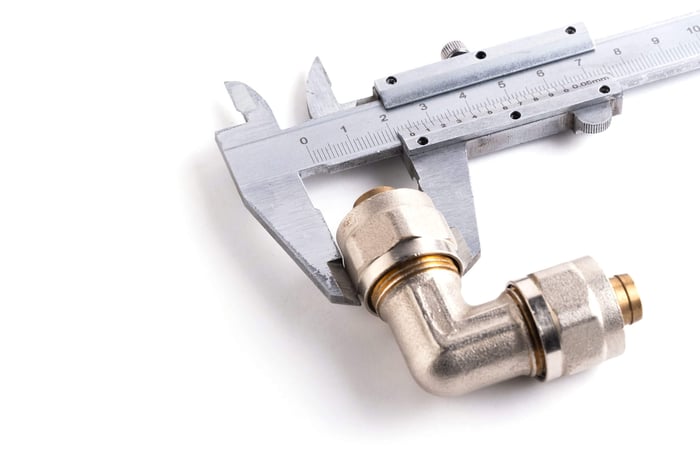
- Measure OD at the large end: Use vernier calipers (not tape measures) and match to the NPT size chart
- Verify TPI: Use a thread pitch gauge for a snug, gap-free fit — common NPT values are 27, 18, 14, 11.5, and 8 TPI
- Confirm thread standard: Cross-check OD, TPI, and thread angle against both NPT and BSP charts to rule out mismatch
- Inspect thread condition: Check for burrs, nicks, corrosion, and galling damage before every assembly
- Count engagement threads: Mark the hand-tight position and count wrench-tight turns to ensure proper engagement without over-tightening
- Apply correct sealant: Match sealant type to material, temperature, and pressure requirements — apply to male threads only
- Pressure test: After installation, test under operating pressure — small leaks rarely stay small
For a complete walkthrough of steps 1–4 with an NPT size chart, see our detailed guide: Understanding and Measuring NPT (National Pipe Thread) Size.
NPT Thread Size Quick Reference
Use this table to identify NPT size based on male thread outside diameter and threads per inch (TPI). Measurements should be taken at the large end of the male thread using calipers:
| Nominal Size | Threads Per Inch (TPI) | Male OD at Large End (inches) |
|---|---|---|
| 1/16″ | 27 | 0.313 |
| 1/8″ | 27 | 0.405 |
| 1/4″ | 18 | 0.540 |
| 3/8″ | 18 | 0.675 |
| 1/2″ | 14 | 0.840 |
| 3/4″ | 14 | 1.050 |
| 1″ | 11.5 | 1.315 |
| 1-1/4″ | 11.5 | 1.660 |
| 1-1/2″ | 11.5 | 1.900 |
| 2″ | 11.5 | 2.375 |
| 2-1/2″ | 8 | 2.875 |
| 3″ | 8 | 3.500 |
| 4″ | 8 | 4.500 |
These dimensions are per ASME B1.20.1 — the governing standard for NPT threads. Nominal size refers to the approximate inside diameter of the pipe, not the outside diameter of the thread.
Build Leak-Free Pneumatic Connections
Proper measurement and installation technique is the single most effective defense against NPT fitting failures. A caliper, a thread pitch gauge, and a reference chart cost less than one emergency shutdown.
PneumaticPlus carries a full line of NPT-threaded components built to ASME specifications:
- Push-to-Connect & NPT Fittings — brass, stainless steel, and composite options
- Brass Pipe Fittings — elbows, tees, nipples, and adapters
- Filter-Regulator-Lubricator (FRL) Combos — protect your system from the contamination that accelerates fitting degradation
- Brass Ball Valves — standard, mini, and full-port configurations
- Solenoid & Pneumatic Valves — NPT-threaded automation components
- Pressure Gauges — monitor system pressure to prevent overpressurization
- Air Regulators — precise pressure control for safe NPT operating limits
Need help selecting the right size or thread type for your application? Contact the PneumaticPlus team or call 800-658-3579.
Disclaimer: This article is intended as educational reference material based on publicly available industry sources and standards (ASME B1.20.1, ASME B1.20.3). It does not constitute engineering advice. For safety-critical, high-pressure, or code-regulated applications, always consult a qualified engineer and follow applicable codes and manufacturer specifications.
FAQs
Q1: Why does my NPT fitting keep leaking even after applying PTFE tape?
A1: Common causes include thread mismatch (NPT vs. BSP), insufficient tape coverage, applying tape in the wrong direction, tape applied to female threads instead of male, or over-tightening that deforms the threads beyond their sealing capability. Always verify TPI and OD with calipers before assembly.
Q2: Can NPT and BSP threads be used together?
A2: No. NPT has a 60° thread angle while BSP uses 55°. Even when TPI values coincidentally match (e.g., both 1/2″ NPT and 1/2″ BSP are 14 TPI), the angle difference creates a spiral leak path that no sealant can reliably seal. Always verify thread standard before assembly.
Q3: How tight should NPT fittings be?
A3: Per ASME B1.20.1, hand-tighten to finger-tight, then add 1.5 to 3 wrench turns maximum for sizes 2 inches and smaller. Over-tightening can crack female ports (especially brass or cast iron) or permanently deform threads. Count exposed threads rather than relying on feel or torque.
Q4: What causes thread galling on stainless steel NPT fittings?
A4: Stainless steel is prone to adhesive wear (galling) where friction causes metal surfaces to cold-weld between threads during assembly. Prevention includes applying anti-seize compound, tightening slowly by hand (avoid power tools), and using dissimilar metals when design allows (e.g., stainless male into brass female).
Q5: How often should NPT fittings be replaced?
A5: NPT fittings should generally be replaced after 2–3 assembly/disassembly cycles. In high-pressure or continuous-duty systems, implement periodic inspection using Go/No-Go thread gauges and replace fittings showing visible galling, scoring, or corrosion pitting. For critical systems, establish a scheduled replacement cycle (e.g., every 5 years).
Q6: Which PneumaticPlus products use NPT threads?
A6: Most PneumaticPlus products use NPT connections, including push-to-connect fittings, brass ball valves, FRL (filter-regulator-lubricator) units, solenoid valves, and air regulators. All NPT-threaded products conform to ASME B1.20.1 specifications. Browse all fittings at pneumaticplus.com/fittings/.
Q7: What's the difference between NPT and NPTF threads?
A7: NPT (National Pipe Tapered) requires sealant (PTFE tape or pipe dope) because its thread geometry leaves a small spiral clearance between crests and roots. NPTF (National Pipe Taper Fuel) has modified thread crests and roots that crush together to create a mechanical dryseal without sealant. Both share the same taper and TPI specifications.